The Controls tab controls the image quality in real-time as seen on the Preview Window. Controls like Exposure, Gain and Frame Rate are contained in this tab.

Please note that the Controls tab will only display the features that are supported by the active Pixelink camera. For instance, if a monochrome camera is connected to the system, the Controls tab will not show features for colour cameras (like White Balance and Saturation).
How to Manipulate the Controls
Exposure

Click on the "Exposure Time" slider and drag to the desired exposure time setting, or enter the exposure time in the box provided. To have the camera determine the exposure time for the current image, click on the Auto Button and a reasonable exposure time will be calculated based on the average intensity of the image. To have the camera perform continuous auto-exposure (where the camera adjusts exposure time based on changes to the image), check the "Continuous" check box.
Click on "Exposure Time" slider and drag to the desired exposure time setting, or enter the setting in the box provided. To have the camera determine the exposure time, click on the Auto Button (or Auto ROI if you desire the operation to be performed only over a specified area) and it will calculate a reasonable exposure time based on the average intensity of the image. To have the camera perform an auto-exposure all the time, check the "Continuous" check box (or Continuous ROI). To set the minimum and maximum allowed values for the exposure drag the slider to the desired position and click Set Minimum or Set Maximum. Click Reset to return the limits to their default values.
To adjust the size and position of the Auto ROI click the Auto-ROI radio button at the top of the preview window. The Auto-ROI box will apply to the Auto ROI Exposure, the Auto ROI Gain and the Auto ROI White Balance.

Gain

The gain controls work in the same way as the exposure controls with the exception that the gain controls do not support Minimum and Maximum bounds on the allowed values.
Note: Gain has the effect of increasing both the video signal and signal noise. Be careful when using this command, it is always preferable to increase the amount of light entering the camera. Use gain only for light starved applications.
Saturation

Color Cameras only
Click on "Saturation" slider and drag to the desired saturation setting, or enter the value in the box provided. A saturation value of 0, converts the image to monochrome. Increasing the slider increases the vibrance of the image. For PL-D cameras, the default Saturation value is 100.
Gamma

The Gamma setting controls the contrast in the image by translating pixel values according to a logarithmic curve. A value of one is a linear translation. Higher or lower values of Gamma will result in missing codes in the image histogram. Please check the "Gamma On" checkbox to turn on this feature. Click on the slider and drag it to the desired setting or enter the value in the box provided.
Frame Rate

Frame Rate allows you to set the frame rate for your camera. With the "Continuous" box checked, the camera will determine a "good" value for frame rate (for PL-D cameras, this is approximately 2/3 of the USB 3.0 bandwidth). To enable manual control of frame rate, uncheck the "Continuous" box. This will allow you to use the slider, or enter a value in the box, to set frame rate.
Some PL-D Cameras with a Sony sensor will also have an option for Fixed Frame Rate mode, which can be enabled by checking the "Fixed" box. See the Special Camera Mode article for more information about this special mode of operation.
Color Temperature

The "Color Temp{K}" allows the you to select the required temperature setting in correlation to the light source being used. It is recommended that this is set before White Balance is performed.
Check the Color Temp{K} "On" checkbox to turn on this feature. Click on the slider and drag to the desired color temperature or enter the setting in the box provided.
Note: There are only three fixed values for color temperature: 3200K, 5000K and 6500K.
White Balance Color Cameras only
The "White Balance" setting allows the user to control the individual red, green and blue channel gains, so that a non standard color balance can be achieved. The "Auto" feature will attempt to white balance the gains (match the histogram peaks of each color channel) based on the image data in the current ROI.
Direct the camera so that the object you wish to be "considered" as white is in the field of view. Click on "Auto" under White Balance (this action will take a few seconds to complete). To perform the white balance over a smaller specified area click "Auto ROI".
Brightness
Some PL-D, PL-U and PL-B only
The brightness slider controls the black level offset of the image. For many camera models, the default value is not 0, and the default value is selected to provide the best image quality. Setting the slider to 0 results in no black level offset being applied.
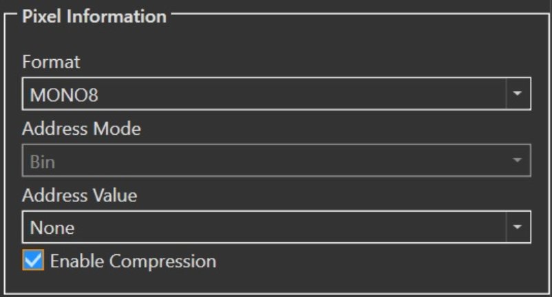
Pixel Format

To select the appropriate pixel format, click on the "Format" drop down menu and select your desired setting. Pixel Formats are camera dependant; the most common being 8-bit monochrome for black and white cameras, and BAYER8 for colour cameras.
Pixel Addressing

The Pixel Addressing feature reduces the number of pixels that are read from the ROI. Pixel Addressing is controlled by two parameters – a Pixel Addressing mode and a value.
The Pixel Addressing mode determines how the number of pixels is reduced. The modes of Pixel Addressing are: decimate (0), averaging (1), binning (2) or resampling (3), but the modes supported will depend on the camera.
The Pixel Addressing value can be considered as the size of a block of pixels that will be reduced to a 2x2 group. With a Pixel Addressing value of "None", the Pixel Addressing mode has no effect and all pixels in the ROI will be returned. For Pixel Addressing values greater than 1, the number of pixels will be reduced by the value. For example, a Pixel Addressing value of 6 x 6 will decrease the pixels to a 2 x 2 block – a reduction of 4/36 or 1/9.
The decimate mode will drop pixels all the pixels in the block except for the top-left group of four. At the highest Pixel Addressing value of 6, a 12 x 12 block of pixels is reduced to 2 x 2. At this level of reduction detail in the scene can be lost and color artifacts introduced.
The averaging mode will average pixels with the similar color within the block resulting in a 2x2 Bayer pattern. This allows details in the blocks to be detected and reduces the effects of color artifacts.
The binning mode will sum pixels with similar color within the block reducing the block to a 2x2 Bayer pattern. Unlike binning with CCD sensors, this summation occurs after the image is digitized so no increase in sensitivity will be noticed but a dark image will appear brighter.
If your camera supports asymmetric pixel addressing, then you can specify different factors to be applied to the horizontal and vertical dimensions. Note that the same pixel addressing mode is applied to both dimensions.
The resampling mode uses a different approach involving the conversion of the Bayer pattern in the blocks to RGB pixels. With a Pixel Addressing value of 1, resampling has no effect. With a Pixel Addressing mode of 2 or more, resampling skips a bayer to RGB conversion step and converts the block of 10-bit pixels to one 30-bit RGB pixel by averaging the red, green and blue channels. Setting the video format to YUV422 mode will result in the best image quality while resampling. Resampling will create images with the highest quality and the least artifacts.
Pixel Addressing will reduce the amount of data coming from the camera, however only the Decimate mode will permit an increase in the frame rate. Averaging, binning and resampling modes have the same frame rate as a Pixel Addressing value of 1 (no decimation).
Pixel Addressing works in the same fashion with color or monochrome sensors.
Compression
Some monochrome PL-D, PL-U, and PL-X cameras only
Enabling compression will allow the camera to output compressed images using our lossless compression scheme. The images are decompressed by the Pixelink software on the host side. This feature reduces the amount of data being transferred over the USB link, and is helpful when running multiple cameras on a single bus.
Compression is only available on certain cameras, and is only compatible with monochrome 8-bit pixel formats.
Orientation

The camera preview can be flipped horizontally and vertically, as well as rotated 90, 180 and 270 degrees clockwise. To flip the preview check the appropriate check boxes and to rotate the preview select the appropriate radio button.
Polar Cameras Only
|  |

For cameras that support polarization there are four available Pixel Formats:
STOKES4_12: Image data is formatted to show the polar images Stokes Values, S0, S1 and S2. The image displayed in the preview window will be the S0 channel.
POLAR4_12: Image data is formatted to show the 0°, 45°, 90° and 135° channels. The image displayed in the preview window is the sum of the 0° and 90° degree values.
POLAR_RAW4_12: Image data represents each of the 0°, 45°, 90° and 135° polar channels. By default, the image displayed in the preview window is the ‘raw’ pixel values of the 45° polar channel.
Note: Enabling "Four Quadrant View" displays all four polar channels in the preview window separately.
HSV4_12: Image data is formatted to show the Intensity, Angle of Polarization and Degree of polarization. The image displayed in the preview window can take one of three forms, selectable in the "Interpretation" drop down box. COLOR, will show an image where the images HUE represent the angle of polarization and the saturation is represented by the degree of polarization. ANGLE, will show an image where the shade of the pixel represents the angle of polarization. DEGREE, will show an image where the shade of the pixel represents degree of polarization.
To increase or decrease the relative strength of each individual polar channel on the camera (0°, 45°, 90° and 135°) adjust the polarization sliders or click the "Min All" and "Max All" buttons.
HDR Cameras Only

For cameras that support HDR (High Dynamic Range) use the "HDR Mode" selection box to select the desired HDR mode. "Disabled" will disable HDR. "Camera" will apply the HDR image improvement algorithm on the camera. "Interleaved" will have the camera send an image composed of the light and dark versions of the image captured by the camera, side by side.
Bandwidth Settings

By default bandwidth for each camera attached to the host system will be automatically allocated. To manually allocate bandwidth select "On" and adjust the slider or enter the desired bandwidth in the text box.
When Limit Bandwidth is enabled, this feature will place an upper bound on the amount of aggregate bandwidth the camera may use for image data. Each individual packet associated with image data must (by definition) be sent at the full link speed, but over a longer period of time, the amount of overall bandwidth consumed by the camera, will not exceed this limit. This feature may be particularly useful if you plan on using multiple cameras on a single bus, or connecting the camera onto a bus that has another high throughput device.
Precision Time Protocol

On supported cameras, the precisions time protocol can be controlled in the Precisions Time Protocol tool. To turn on PTP click "on". To turn on Slave Only mode click Slave Only. The current state of the camera as well as the camera's self reported time are displayed in the "State" and "Camera Time" areas.
Navitar LED Controllers
With one or more Navitar LED controllers connected, select the COM Port of the LED Controller you would like to adjust. Use the slider or text box to adjust the brightness of the LED controller from between 0 to 100

Note: The Controller Settings section is only shown when an LED controller is connected, and powered on. If these settings are not visible, double check that the LED controller is powered, and connected to your system via USB.